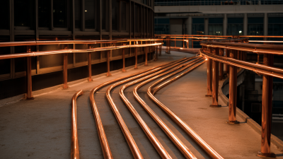
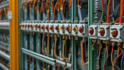
Choosing a Copper Dense Busway is not simply a matter of selecting the highest current rating. The system must suit the building’s electrical load, available space, installation route, and plans for future expansion. A unit that fits a drawing may still be difficult to install around beams, pipework, or existing equipment. Measure the route carefully.
Start by confirming the required voltage, rated current, fault withstand capacity, and expected load profile with a qualified electrical professional. Then compare conductor size, insulation, enclosure protection, joint design, and temperature limits using the manufacturer’s technical documents. Copper offers strong electrical conductivity, but performance depends on the complete assembly, not the conductor alone. Details matter.
Consider the actual site conditions. Dust, moisture, heat, vibration, and restricted access can affect product selection and maintenance planning. Check that the chosen busway’s protection rating and installation requirements fit the environment. Review the supports, connection points, tap-off positions, and clearance needed for inspection. A small layout oversight can become an expensive site problem.
Reliable decisions also depend on traceable specifications, applicable product certifications, and clear installation instructions. Ask suppliers for test reports and technical drawings, and compare like-for-like ratings rather than relying on headline figures. Some project details may remain uncertain until the route is surveyed; acknowledge that early. The best choice is a Copper Dense Busway that meets documented electrical needs, fits the real installation, and can be inspected and maintained safely over time.
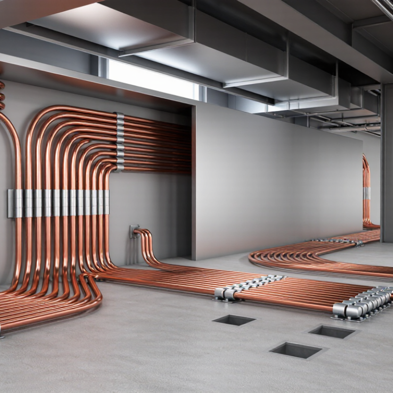
Assess the electrical load before choosing a copper dense busway. Build a schedule of connected equipment, expected demand, and planned additions. Check peak demand, not just average consumption. Motors, welders, and other equipment can create brief surges that affect capacity and protection. Also review voltage drop, fault current, ambient temperature, enclosure conditions, and harmonic-producing loads. A busway’s usable rating depends on its complete installation, not conductor material alone.
Growth can change the answer. Lawrence Berkeley National Laboratory’s 2024 United States Data Center Energy Usage Report estimates that U.S. data centers used 176 terawatt-hours in 2023, about 4.4% of national electricity consumption. That figure is not a sizing rule for other facilities. It does show why concentrated, expanding loads deserve careful forecasting. A tidy spreadsheet can still miss a real-world peak.
Tips: Compare equipment nameplate data with measured demand where available. Check load profiles during busy shifts, and leave suitable capacity for planned expansion. Record assumptions; revisit them when operations change. Small details matter. A qualified electrical engineer can verify calculations, protection coordination, and applicable installation requirements.
Start with the system voltage, not the busway’s appearance. Confirm nominal voltage, frequency, phase configuration, and grounding arrangement against the electrical design. The insulation rating must suit the system and its operating conditions. A mismatch is not something to work around.
Size continuous current using the calculated load, expected demand, and planned expansion—not only the largest machine nameplate. Check ambient temperature, enclosure, installation orientation, and nearby heat sources, as these can affect allowable current. Keep some margin. Too much margin can mean unnecessary cost and bulk, so review that trade-off carefully.
Short-circuit rating needs equal attention. Obtain the available fault current at the busway location, then verify that the busway’s tested withstand rating is adequate for the system and protective-device clearing time. Check upstream breaker or fuse data, including current-limiting behavior where applicable. A panel schedule alone may not tell the whole story. One overlooked assumption can skew the result. Use current test data and have a qualified electrical professional confirm the ratings and installation details before selection.
Evaluate the installation before selecting a copper dense busway. Record the available ceiling height, ambient temperature, moisture, dust, and access for maintenance. A route above a hot process line may need different spacing or protection from one in a clean electrical room. Check bends, tap-off positions, and structural supports against the actual building drawings. Small offsets matter.
Routing also needs room for thermal movement. The Copper Development Association’s copper data sheet reports a linear expansion coefficient of about 16.9 µm/m·°C. A 30-metre run warming by 40°C could therefore expand roughly 20 millimetres. Allow for movement as specified by the busway design, and confirm support locations before installation. IEC 61439-6:2012 sets verification requirements for busbar trunking systems; use it alongside the project’s equipment documentation. Do not assume a corridor shown as clear will stay clear. Pipes, fire barriers, and later service work can change the route. I would recheck the longest run and its expansion provisions late in design, even when the drawings look settled. That check is easy to miss.
Shorter routes can reduce material and simplify installation, but the best option must also meet required clearances, support spacing, bend limits, and access needs. Values are an illustrative planning example; verify dimensions with a site survey and the selected busway system’s installation requirements.
Compare Copper Conductors, Insulation, and Enclosures
Copper dense busway selection starts with the actual load, not just the largest rating on a catalog page. Check continuous current, expected temperature rise, fault withstand, and available installation space. Copper conducts efficiently, but bar thickness, joint design, and cooling conditions also affect performance. A heavier conductor is not automatically better; it can add weight and cost without solving a layout or ventilation problem. Verify ratings against the project conditions.
Tips: Compare insulation by temperature rating, dielectric strength, and resistance to moisture or dust. Ask how joints are insulated and inspected. Small gaps matter. Choose protection suited to the site, not just the product sheet.
The enclosure protects conductors and supports heat dissipation. Indoor equipment in a clean electrical room may need different protection from busway near washdown areas or dusty production lines. Consider corrosion exposure, ingress protection, mounting orientation, and access for maintenance. A compact enclosure can save space, yet tight clearances may complicate installation or servicing. Review drawings with the installer, and confirm that the specified busway fits the route, supports, and connection points. Some assumptions will change after a site walk; document those changes before ordering.
A copper dense busway should be judged by verified performance, not its enclosure alone. Check that its design and test documents reference the standards required in your market, such as IEC 61439-6 or UL 857. Ask for evidence covering temperature rise, short-circuit withstand, protective bonding, and enclosure ratings. These details matter in a crowded electrical room, where heat, dust, and access limitations can affect service. The Copper Development Association reports annealed copper conductivity at 100% IACS, or about 58 MS/m at 20°C. That material benchmark is useful, but it does not prove the complete busway’s performance.
Tips: Match the busway rating to the load profile and installation conditions. Request test records, installation clearances, joint-torque requirements, and guidance for expansion or future tap-offs. Look closely at plug-in unit interlocks and verify that protective devices coordinate with the available fault current. Small omissions can become expensive.
Support is part of the specification. Confirm who provides commissioning advice, replacement joints, and compatible tap-off units, and ask how quickly technical help is available. Keep drawings and inspection records with the equipment. A technically compliant product can still be difficult to maintain if documentation is vague. I would also check service access on site; paper layouts sometimes miss real obstructions.
| Selection Dimension | What to Verify | Practical Selection Guidance | Evidence to Request |
|---|---|---|---|
| Applicable product standard | Confirm the busway is designed and tested to the standard required for the project location and application. | IEC 61439-6 applies to busbar trunking systems. In the United States, UL 857 covers busways. Confirm the applicable edition and local authority requirements rather than assuming one standard applies everywhere. | Declaration or certificate of conformity, listing details where applicable, and the product’s standard and edition. |
| Electrical rating | Check rated operational voltage, frequency, and continuous current rating for the complete assembly. | Select ratings to suit the system design and load. Account for ambient temperature, installation conditions, enclosure, and any derating specified by the manufacturer. | Published rating tables, technical data sheet, and project-specific sizing calculations. |
| Short-circuit withstand | Verify the busway’s short-time withstand and peak withstand ratings, and the conditions under which they apply. | Ratings must be coordinated with the prospective fault current at the installation point and the upstream protective device. Do not compare a busway rating without checking the test configuration and protection assumptions. | Short-circuit test information, fault-current coordination details, and protective-device requirements. |
| Copper conductors | Confirm conductor material, configuration, insulation system, and whether the stated current rating applies to the selected arrangement. | Check that copper conductors are specified for all required phases and that joints and connections are rated for the system. Review neutral and protective-conductor arrangements separately. | Conductor schedule, construction details, joint data, and temperature-rise test information. |
| Neutral and harmonics | Determine the neutral conductor rating and whether the load includes significant nonlinear equipment. | Loads such as IT equipment, LED lighting, and variable-speed drives can produce harmonic currents. Have a qualified electrical designer assess neutral loading and specify an appropriate neutral arrangement. | Neutral rating options, design assumptions, and load or harmonic study where required. |
| Grounding and bonding | Check how protective earthing is provided and how joints maintain electrical continuity. | Verify the intended protective-conductor path, bonding provisions, and compatibility with the installation’s earthing system. Follow the applicable electrical code and installation instructions. | Earthing and bonding diagrams, joint details, and installation instructions. |
| Enclosure and ingress protection | Match the enclosure protection level and materials to the actual environment. | Consider indoor or outdoor exposure, dust, moisture, corrosion, cleaning practices, and temperature. Select the required IP rating under IEC 60529 where applicable; an IP rating alone does not establish suitability for every environment. | Enclosure rating, environmental limitations, materials information, and any relevant test reports. |
| Plug-in outlets and tap-off units | Verify outlet spacing, compatible tap-off units, current ratings, and protective-device options. | Choose an arrangement that supports planned loads and safe access. Confirm any mechanical interlocks, shutters, and restrictions on connecting or removing units under load. | Tap-off unit data, compatibility schedule, operating instructions, and interlock details. |
| Fire and building interfaces | Review penetrations through fire-rated walls or floors and any required fire-stopping system. | Use a fire-stop solution suitable for the specific busway, opening, and rated construction. Confirm the installation preserves the required fire-resistance performance and follows local building rules. | Approved or tested fire-stop details, installation method, and project-specific coordination documents. |
| Route, joints, and installation | Check the route, clearances, supports, joint access, expansion needs, and alignment tolerances. | Coordinate straight lengths, elbows, risers, end feeds, and supports with the building layout. Follow the manufacturer’s specified joint assembly and torque procedure; do not assume components from different systems are interchangeable. | Coordinated layout drawings, support spacing, jointing procedure, and required installation tools. |
| Inspection and commissioning | Establish the inspections and electrical tests required before energization. | Use the applicable code and manufacturer instructions to define checks such as visual inspection, connection verification, protective-conductor continuity, and insulation testing where appropriate. | Commissioning checklist, test procedures, torque records, and maintenance guidance. |
| Technical support and documentation | Confirm that engineering assistance and complete project documentation are available. | Seek support for layout review, load changes, coordination, installation questions, and replacement parts. Confirm response arrangements and the availability of current drawings and instructions. | Support contact process, document list, training options, and parts or service availability. |
| Warranty and lifecycle | Review warranty coverage, exclusions, maintenance requirements, and expected availability of compatible components. | Compare the written terms and lifecycle support needed for the project. Confirm that future extensions or replacement tap-off units can be sourced and are compatible with the installed system. | Written warranty terms, maintenance schedule, and compatibility or spare-parts information. |
Note: Final selection, installation, and protection coordination should be completed by qualified electrical professionals in accordance with the project specifications, applicable codes, and the busway manufacturer’s instructions.